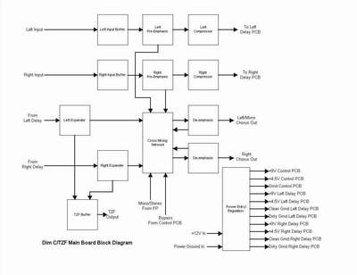
A Pictorial Tour of the Dim C/TZF Board Construction
The DimC/TZF remains one of my fondest builds. It's a device that I use nearly all the time, particularly when I'm using polyphonic synthesizers.
But, beyond that, it is a reminder to me of my friend, Jeff Pontius, who passed away in 2006. Jeff was an amazing guy, and an amazing musician and synthesist. Not a day goes by that I don't think of him and miss him. This project was a true collaboration between the two of us and remains one of my most musically useful projects to this day.
Jeff was in charge of designing the panel and final assembly, and my task was to design, build and test the boards. After I had assembled the boards, I applied labels to each of the wires hanging from the boards, and a mark-up sheet to designate the connections with the final assembly.
We built two Dim C/TZF units - one for myself, and one for Jeff.
The functions of each Dim C/TZF are divided into four PCB's:
1. The Main PCB
This board handles all of the audio functions such as input buffering, pre-emphasis, compression, expansion, signal mixing, and de-emphasis. It also serves as the power input module and contains the 9V regulator and 1/2 VCC divider.
2. The Control Board
This board contains the bypass debounce and logic, the LFO, and the CV processing circuitry.
3. Delay Board 1
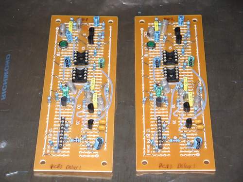
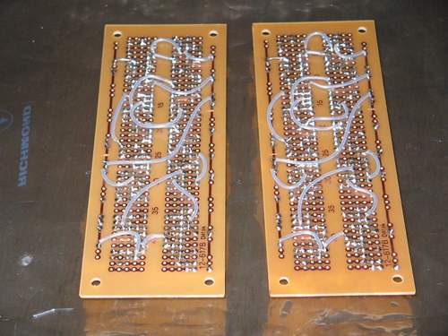
This board is the 'left' channel delay module. It contains the antialiasing filters, BBD, and clock for the 'left' delay line. It also provides +7V regulation.
4. Delay Board 2
This board is the 'right' channel delay module. It contains the antialiasing filters, BBD, and clock for the 'right' delay line.
Main Board Construction
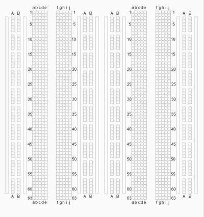
For the main board, I used protoboard that I obtained from Futurlec. I really like these boards, because they provide 8 solid bus traces in which to distribute power, ground and other common signals. The trace side of the board contains a legend that makes it easy to lay out components and jumpers before work begins. Here is a facsimile of the board layout:
 |
The satellite boards (boards 2, 3 and 4) were built on a much smaller protoboard that I purchased from MCM.
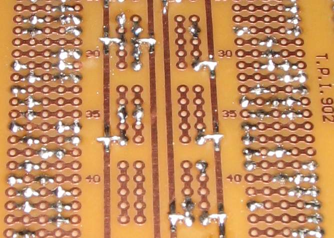
When working with this board, I use the busses for distributing supply voltage and ground. In this application, some of the busses are used to disribute 9V, some are used to distribute 1/2Vcc (4.5V), and others are used to distribute ground. At the A and B vertical pads, I will then solder wire to the bus and then to one of the pads of the five hole vertical group. This frees up other vertical pad groups and negates the need to bus all of the vertical pads together to form a single bus. This also allows me, when needed, to subdivide the solid vertical busses by cutting the trace and running different signals on different sections of the vertical bus.
 |
After laying out the board and checking the layout several times against the schematic, it was time to begin construction of the main board.
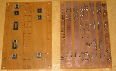
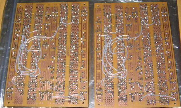
Unfortunately, these boards do not have mounting holes, so the first step was to drill mounting holes in each corner. Then, I cut one bus trace with exacto blade in order to distribute ground to section that did not have ground adjacent to it. I also used a spot face cutter to cut one trace that was needed for a resistor that is mounted on one of the vertical 5 pad traces. The next step was to solder in the bus traces to the points needed on the board. After that, the sockets were soldered in. Note that I actually built two of each board (one for Jeff and one for myself).
 |
After that I added the components and more jumpers to the top side of the board.
 |
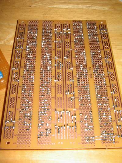 |
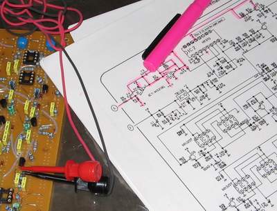
Following that, I added the final top jumpers, put in the bottom jumpers, and added 0.1 uF bypass caps to all of the IC's. The next step was a final trace-through for each board checking for improper connections.
 |
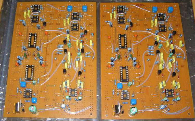
This is how the main boards finally turned out.
 |
 |
Delay Board 1 (Left Delay Line)
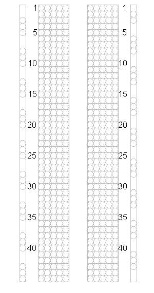
These boards use protoboard that I purchased from MCMInone - handy little boards to have around. They have 45 rows of 5 hole traces arranged in two columns, with bus lines down each side.
The bus lines do not have a hole for every 5 hole pad that is adjacent to them, but there are plenty of them to use.
Below is a facsimile of the layout of the protoboard.
 |
Below are some pics of the finished Delay 1 boards.
 |
 |
Delay Board 2 (Right Delay Line)
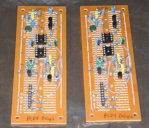
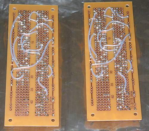
Below are pics of the component and trace sides of the completed Delay 2 boards.
These boards are nearly identical to the Delay 1 boards, except they do not have the +7V regulator or 3.5V divider on them.
 |
 |
Control Board
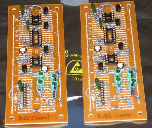
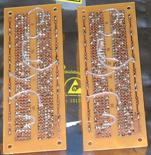
Below are pics of the completed Control Boards, which house the LFO, Bypass Logic, and CV/Manual processing circuit.
 |
 |
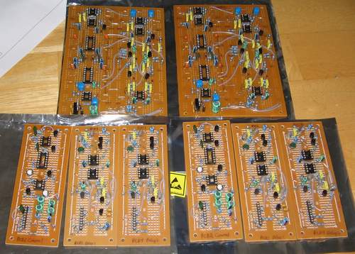
Here's a pic of all of the boards for both Dim C's!
 |

